A free flight rubber band-powered plane is almost a rite of passage for those interested in making things that fly. You can get pretty decent flight times from very affordable, small, and simple designs, and it’s a great way to learn the art of ‘trimming’, tweaking, and tinkering to get the flight characteristics you want. For this ‘powered’ free flight, there are other alternatives, but electric free flight is a nice, affordable, quiet and cheap-to-run hobby.

There are lots of designs out there to build electric planes that carry a small LiPo cell and a timer circuit, so that the propeller is only driven for a short and specific amount of time – often, less than a minute. This is an excellent approach, but there’s a little bit of a weight penalty carrying a battery and also a bit of complexity in building a timer circuit. The electric option we’re going to look at is using a supercapacitor to drive a motor and propeller, adjusting the amount you charge the supercapacitor to change the driven flight time.
Free foam kits
You can actually buy small foam gliders with motors, propellers, and supercapacitors fitted. Whilst we are sure many of these are excellent, we were introduced to supercapacitor flight as a member of a local indoor flying club had bought some of these for resale. On arrival, all the foam components were damaged, the member was refunded, and they presented us each with some of the below par kits for us to pillage the drive systems from. This, in turn, led us into exploring DIY supercapacitor setups made from components, and building, flying, crashing, and rebuilding lots of test aircraft!
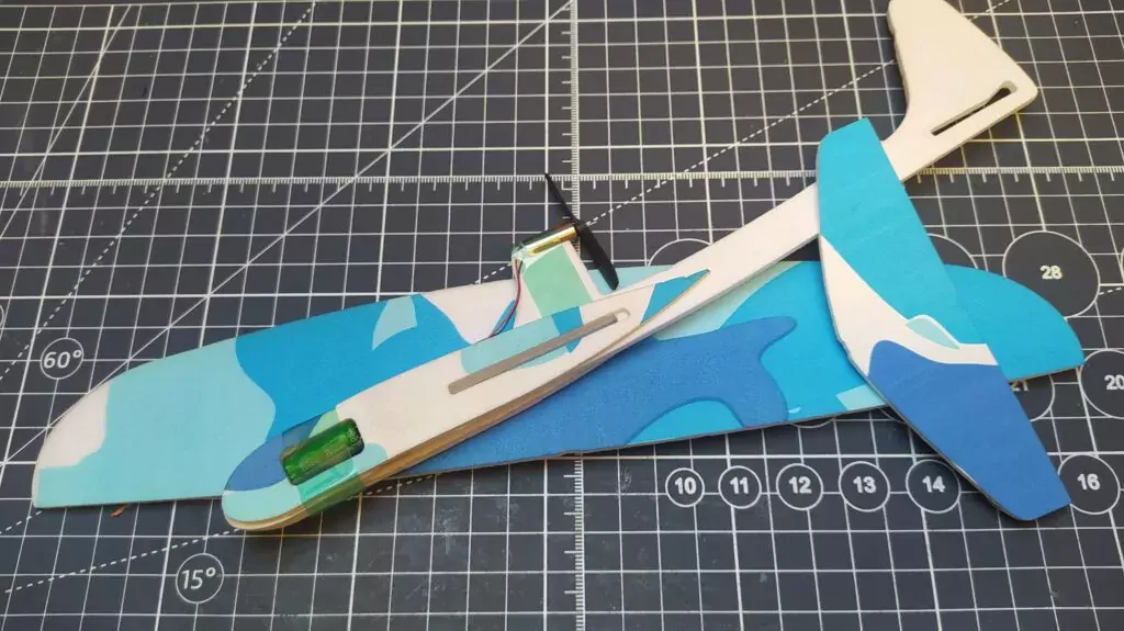
The donated foam kits, Figure 1, have a small 6 × 20 mm brushed motor set up in a pusher formation, where the motor and prop are pointing towards the rear of the aircraft. The system ‘pushes’ the air back over the rear of the aircraft, creating a forward thrust. This is a nice approach for a variety of reasons; including that, if your aircraft crashes, the motor and propeller aren’t the first thing to hit the ground and are a little protected. Looking at this setup from the rear, the motor is spinning counterclockwise and the propeller blades are angled to work in this direction of rotation. The donor foam kits are fitted out with a 5-farad supercapacitor, and this is mounted onto a PCB which has a tiny barrel jack connector. The idea is that you connect a battery pack to the system with a barrel jack and this charges the capacitor. On the donor system, the PCB has a surface-mount LED that indicates the level of charge, increasing in brightness as the supercapacitor charges. As soon as you disconnect the barrel jack, the supercapacitor starts to discharge through the motor and the propeller starts spinning. It will run with some gusto for around 30–40 seconds and will continue to spin at lower power for a couple of minutes.
The majority of supercapacitors that get used for free flight model flying are rated at 2.7 V and, indeed, the ones attached to the donor foam gliders are such. Therefore, we were a bit surprised that the kits came with a 4 × AA battery box, as this provides far too high a voltage. In fact, we sacrificed one kit trying it out and it definitely caused the supercapacitor to lose capacity quite quickly. It’s more common for people to charge these using 2 × AA batteries in a battery box, and this has worked well for these donor supercapacitor setups, as well as our later DIY versions. If you get really fancy, you can develop a constant current charge system to really dial in accurate charges, but we’ve found two AAs to be perfectly adequate.
First attempt
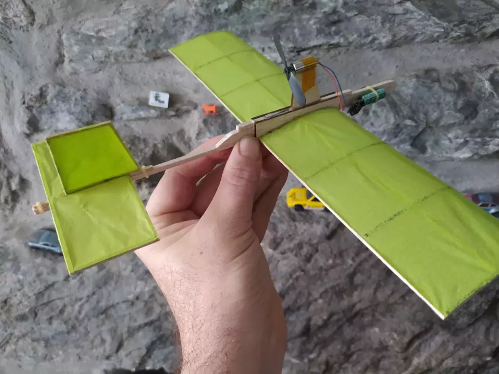
For our first attempt, we used the salvaged supercapacitor setup from the foam kit and decided that it would be a sensible idea to try and make the build roughly similar in terms of weight and dimensions (Figure 2). We decided to go with a lightweight balsa frame covered with tissue paper which is a traditional way of aeromodelling. Aiming for 9.5 grams, we made two wing sections that were around 7 cm by 12 cm in size, and attached them to a U-section that slotted over a 3 mm wide balsa fuselage section. We similarly made a tail section with a horizontal stabiliser, and a vertical surface that had a small hinged section to act as a rudder. As this was an experiment, we made the flight surfaces, the wing and the tail, so that they were held on by tiny rubber bands. Making it so that we can move and reposition the components on the aircraft is a great idea when you are working with a new design and want to try out ideas. We tend to err away from the massively complex fluid dynamics engineering of plane design and used some rules of thumb, such as making the tail horizontal surface around 20% of the surface area of the main wing. We cut a small balsa ‘pylon’ which lifts the motor and prop so that it is clear of the fuselage. We tacked the motor onto the pylon with a spot of superglue, but we attached the PCB and supercapacitor with a rubber band so we could again move this up and down the nose end of the fuselage to move our centre of gravity a little.
Wing redesign
Testing the little model revealed that we had designed the wing with too much under-camber and perhaps needed more of an angle of incidence (the angle where the wing points upwards a little at the front when compared to the flat rear stabiliser). It also perhaps had a little too much weight – this meant that we could get reasonable flight characteristics from it whilst the motor was creating some thrust, but it would fall out of the sky when the air speed slowed. That said, we managed to get it trimmed to the point where it would fly a large diameter lap of a gymnasium smoothly and then glide into land. It was certainly encouraging enough to make us explore more.
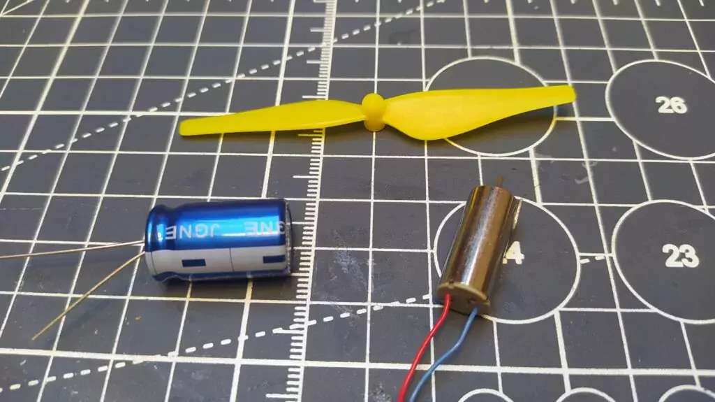
For our DIY build, we needed to come up with a way to charge a supercapacitor and a way to switch the motor system on and off, whilst not adding masses of weight. We decided to take a step up slightly in size of motor and supercapacitor to give us a little more thrust to play with. We ordered some 8 × 20 counterclockwise (CCW) brushless motors and a couple of different capacity supercapacitors, 6.8 F and 10 F (Figure 3). We wanted to stick with a pusher-type approach and so we used some larger 80 mm propellers which are some spares that we had for our small Ryze Tello quadcopter. You can buy sets of these online quite cheaply, and they fit directly onto the shafts of the 8 × 20 mm motors. You get different propellers in a quadcopter set, as different corners of a quadcopter rotate differently, but you are looking for the CCW-marked propellers within the set of four.
‘Power pod’
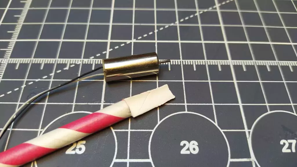
We’ve made numerous test aircraft using this same setup where all the supercapacitor, motor, charge points, and wiring are attached to a paper drinking straw that acts as the plane fuselage. It’s a handy system that could be transformed to a variety of different plane experiments and so we’re calling it a ‘power pod’. The idea is straightforward. At one end of the paper straw is the motor. We’ve begun by cutting away a section of the straw about 15 mm long, but leaving a part of the straw that we can add a dab of glue to and mount the motor (Figure 4).
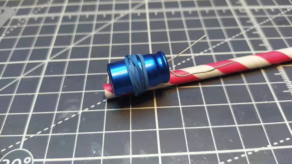
We’ve used a small dot of superglue to attach the motor with the back of the motor case pushed up flush to the straw. Don’t worry if this feels a little flimsy at this point, as we usually reinforce this section when we attach it to a plane. At the other end of the straw, we tend to attach one of our larger supercapacitors, non-permanently with a rubber band (Figure 5).
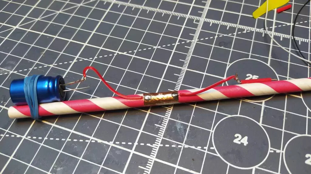
Somewhere towards the middle of the straw, we added two small sections of sticky-back copper tape. We’ve experimented before with this tape, and enjoy cutting conductive parts from it, either by hand or using a vinyl cutter. Our tabs are around 6 mm wide and about 12–15 mm long. Make sure that each tab is on opposite sides of the straw and that they are not contacting each other, as these copper tabs are going to be our charge points (Figure 6).
Next, find a small plastic straw where the hole is around 1 mm diameter. A good option for these is the types of tubes that come with cans of spray oil, such as many types of general lubricant. Another source is some soft drinks cartons that use similar small-bore straws. Cut around 15 mm of the straw off and then cut a small piece of stiff wire; we’ve used MIG welding wire, but a guitar string would work similarly. Bend around 5–7 mm of the wire into a right angle and slide it into the straw section you have just cut. When fully inserted, you should have 3–5 mm of wire poking out of the other end of the short straw section.
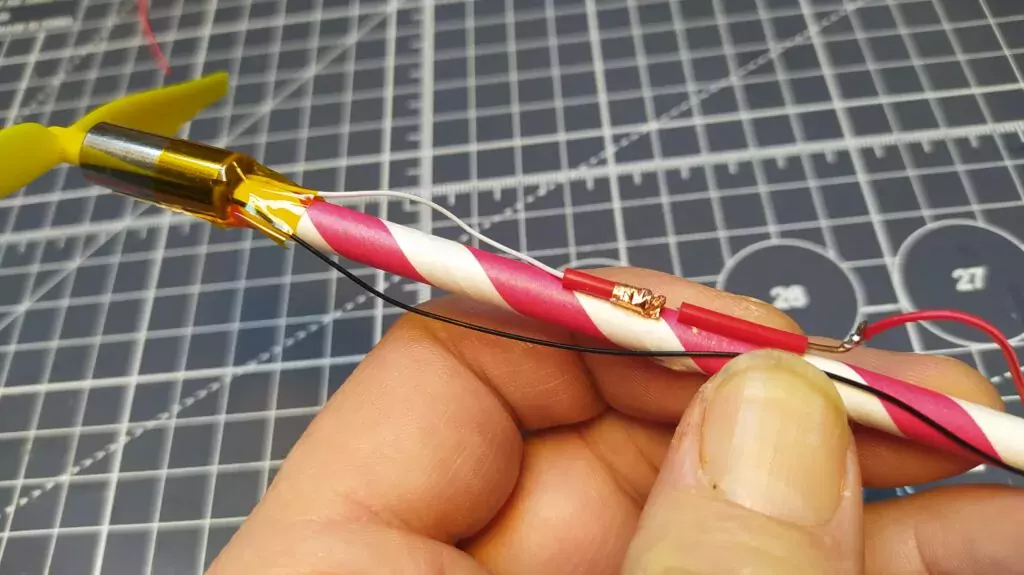
Take the wire out of the small straw section and then glue the small plastic straw section onto the paper straw in the position you want the switch to be, but between the copper tabs and the motor; we’ve tended to use a drop of superglue for this. On the wire that you cut and bent, lightly sand the bent handle section so that it’s clean enough to solder to. Cut a short length of thin, flexible wire and strip a short section of insulation off each end. Wrap one of the uninsulated ends around the stiff wire switch bent section and solder them together. Once cooled, place your switch wire into the small tube glued to the straw (Figure 7). Take the other end of that wire and solder it to the right-hand edge of one of the copper tabs, the end of the tab closest to the motor. This is going to be the positive side of the circuit.
Next, solder a short flexible section of wire to the positive lead on the supercapacitor, and then solder the other end of that wire to the left-hand side of the positive copper pad that we connected the switch wire to earlier.
On the opposite side of the straw, solder a wire between the negative lead on the supercapacitor and the closest edge of the copper tab to it. Then solder the negative motor wire to the opposite end of the same copper tab. This means the motor is always connected to the negative lead of the supercapacitor.

To finish the positive side of the circuit, we are going to cut another section of the small tube/straw we used earlier. Cut around 5–6 mm and thread it over the positive wire attached to the motor. Next, strip around 12 mm of insulation off the end of the motor positive wire and pull the short length of tube up towards this uninsulated section. Then wrap the uninsulated section around the end of the short length of tube and stick it into place by covering it with a thin strip of the conductive copper tape. Squash this all together so that you have a small bundle of copper tape at the end of the tube which is connected electrically to the motor positive wire. Now glue the plastic tube in such a position that it is close to the other switch tube section and that, when you push the MIG wire section all the way in, it will touch the copper pad on the motor-connected side. However, you should be able to move the MIG wire section back to create a gap in the circuit (as in Figure 8).
Power charge
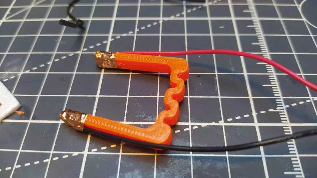
To charge our capacitor, we are going to press a positive and negative contact onto the pads on each side of the power pod assembly we’ve created in the previous section. We used FreeCAD to make a tiny spring clamp (Figure 9), but you could make something similar perhaps by using a laundry peg with some kind of limiting block. The 3D-printed clamp is available on Thingiverse and it has worked really well. The clamp has two holes at the upper end of each side, and we have used the same technique as we did for the switch on board the power pod. We stripped the positive and negative leads coming out of a 2 × AA battery box, salvaged from a broken set of LED lights, inserted the stripped wire sections and wrapped them around the clamp ends. Securing this with copper tape, it creates a positive and negative clamp connection we can touch to the copper pads.
To charge the system, open the switch on the power pod and then gently press the clamp pads onto the correct pads, being really careful to check polarity! It would be easy to touch the clamp to the incorrect pads, which is unlikely to be dangerous, but isn’t going to prolong the life of the supercapacitor. You can experiment with your own systems, but for our 10 F supercapacitor, we find counting to around twelve seconds gives it a good charge. You can then carefully slide the switch wire over to close the circuit and the motor should run.
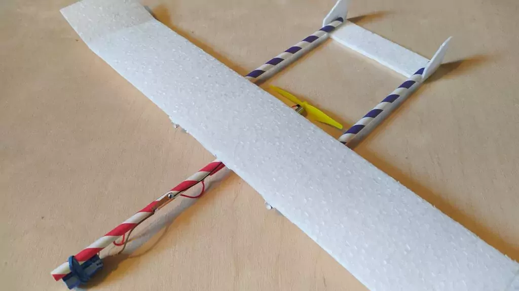
We don’t totally know why, but we have become obsessed with the idea of building a free flight twin-boom plane, where the motor and pusher propeller sit between the rear tail booms (Figure 10). It’s a nice design for our power pod approach and you get a fairly straight thrust line through the fuselage as it’s all essentially a straw. We haven’t quite perfected the plane with each iteration (currently testing Mk4 and building Mk5 at time of writing), but we can happily share some rough dimensions and ideas.
Weight matters
First of all, we are building as light as possible! To enable this, we are using some 2 mm foam that comes on a roll and is sold as an insulation product that can be adhered to walls under wallpaper. We’ve seen a couple of brands, but the most common is ‘Diall’ and you can buy a ten-metre roll for around £6.50. It’s very light and very thin, so we have been laminating two pieces together to form our main section of the wing. As the foam is supplied as a roll, it naturally has a very shallow curve to it, which plays to our advantage when making a slightly aerofoiled wing. We’ve been sizing the wing at around 8 cm ‘chord’ length (the shorter direction) and between 28 and 36 cm wide. We cut two sections to size using a steel ruler and a sharp craft knife, and then glued these sections together. We’ve found that a lightweight bond can be made by brushing the pieces with slightly watered-down PVA glue, but you need to leave this to cure for a full day and, whilst light, it isn’t the strongest. As a compromise, we have tended to stick the front edge of the wing and the wing tips using UHU Por, which is a foam-safe glue, and the rest of the wing surface with watered-down PVA. This combination of glues means that the wing can be handled after an hour or so and the UHU reinforces the leading edges which take some abuse on landing.
Twin-boom design
All our twin-boom design attempts so far have included adding some small dihedral tips to the wing ends. These have been between 4 and 6 cm in length, and you need to carve the connecting end slightly so that when you glue it to the wing, it makes a neat joint. We’ve tended to angle ours upwards at around 20 degrees, and these tips definitely create a more stable and self-correcting glide.
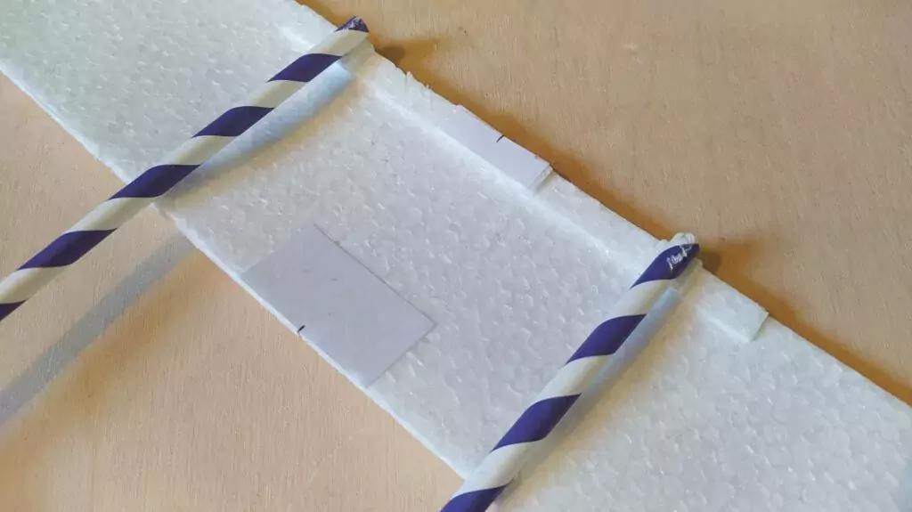
We’ve positioned the booms based on having enough space for the propeller to swing between them and also to give a reasonable tail surface area. The latest iteration uses an 80 mm propeller, and we have the booms spaced out at 10 cm. We have built up the front edge of the wing with around 5 mm of foam and paper to both lift the angle of incidence of the wing and also reinforce the design. The wing therefore sits at around a 3-degree angle compared to the horizontal tail section (Figure 11). This helps to generate lift, but as we say, feel free to experiment widely and share your results!
The 10 cm by 3 cm tail section is made from a single layer of the 2 mm foam, so whilst it’s fragile, we can also flex it a little to bend in angles to create lift and, similarly, we can use the small foam vertical tails to create small rudder angles. We’re aiming to get the aircraft to climb up in a few circles for around 15 to 20 seconds before gliding back down. We can’t say we are 100 percent there yet, but it’s great budget fun and a brilliant challenge!
HackSpace magazine issue 65 out NOW!
Each month, HackSpace magazine brings you the best projects, tips, tricks and tutorials from the makersphere. You can get HackSpace from the Raspberry Pi Press online store or your local newsagents.